Any carrier based PWM technique is done using either a sawtooth or a triangular carrier (at least to the best of my knowledge) But ever asked yourself: Why do we restrict ourselves to these two carriers in particular? What is the criteria of which we decide that a certain carrier is suitable?
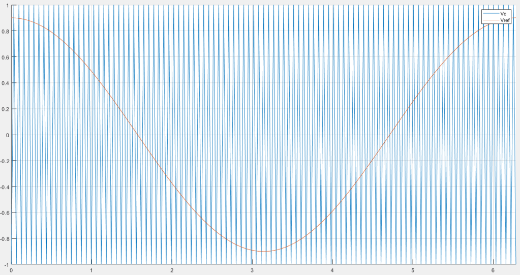
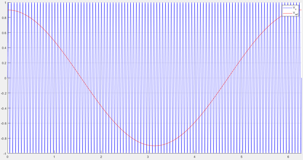
To Answer these questions we must first explain the purpose of a carrier. So lets take a closer look at what actually happens during each carrier cycle. If we consider the following PWM operations.
Triangular Carrier
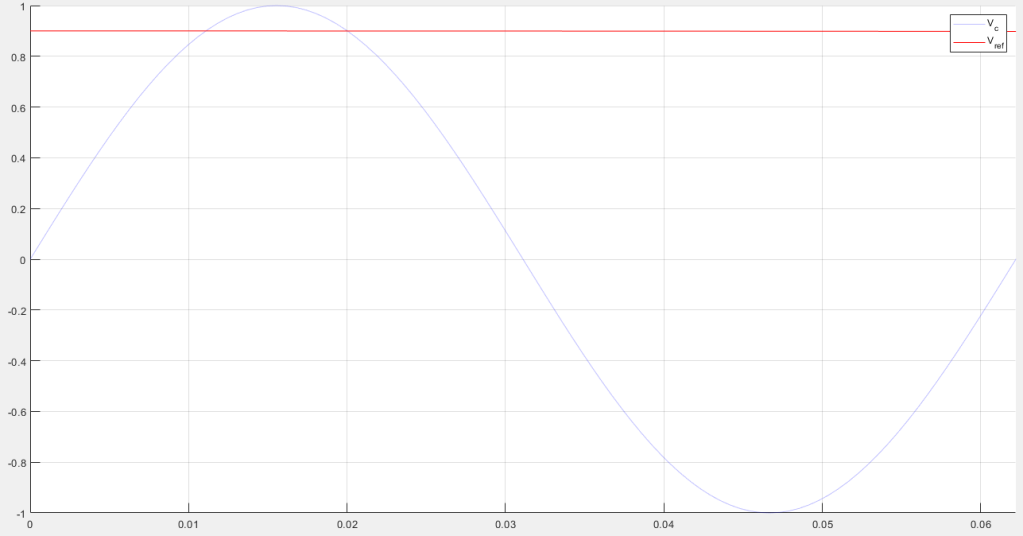
Lets zoom in further into only 1 cycle of the triangular carrier to analyze it

And As usual, when Vref >= Vc then the output Vout = +Vdc or -Vdc otherwise.
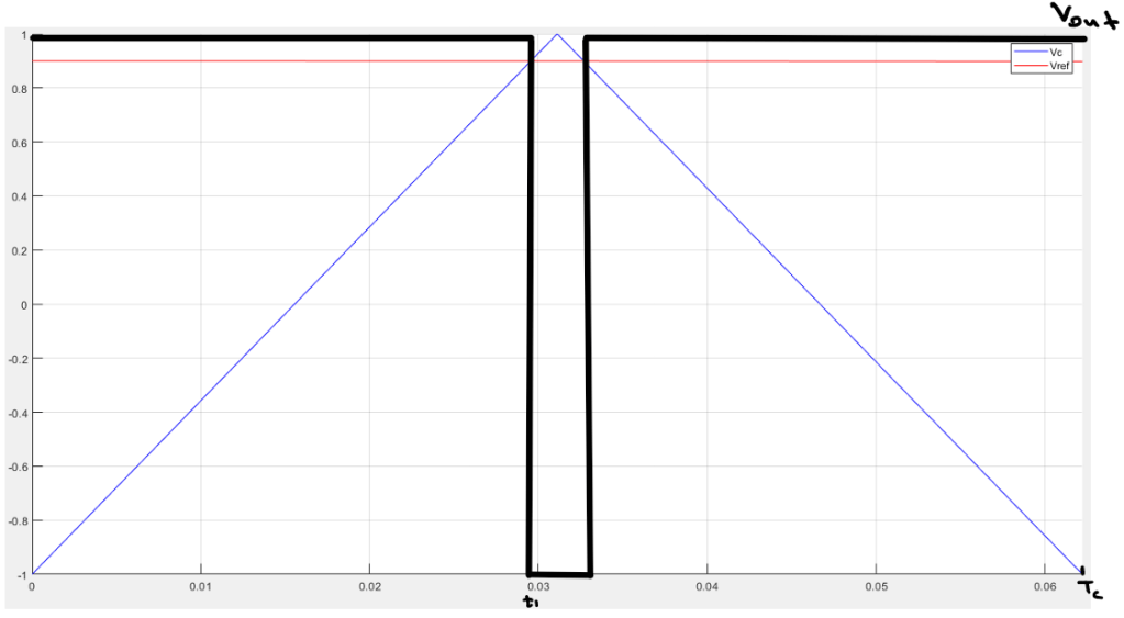
Our ultimate objective from the PWM operation is to produce an output that replicates the reference we provide. In other words, Vout here must be a replica of Vref . Although, Vout is clearly not a copy of Vref , but if we observe it carefully we will find that the average value that Vout produced and the average Vref value are exactly the same.
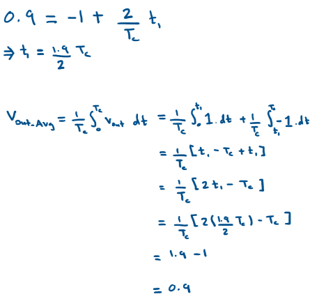
Lets calculate the averages to test this claim
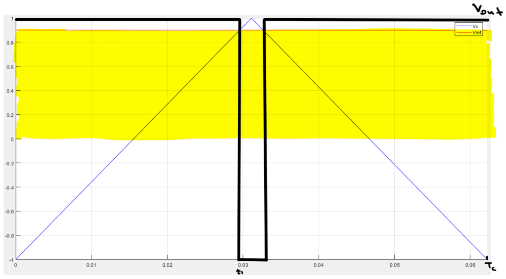
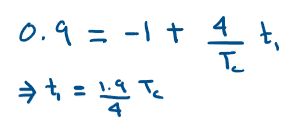
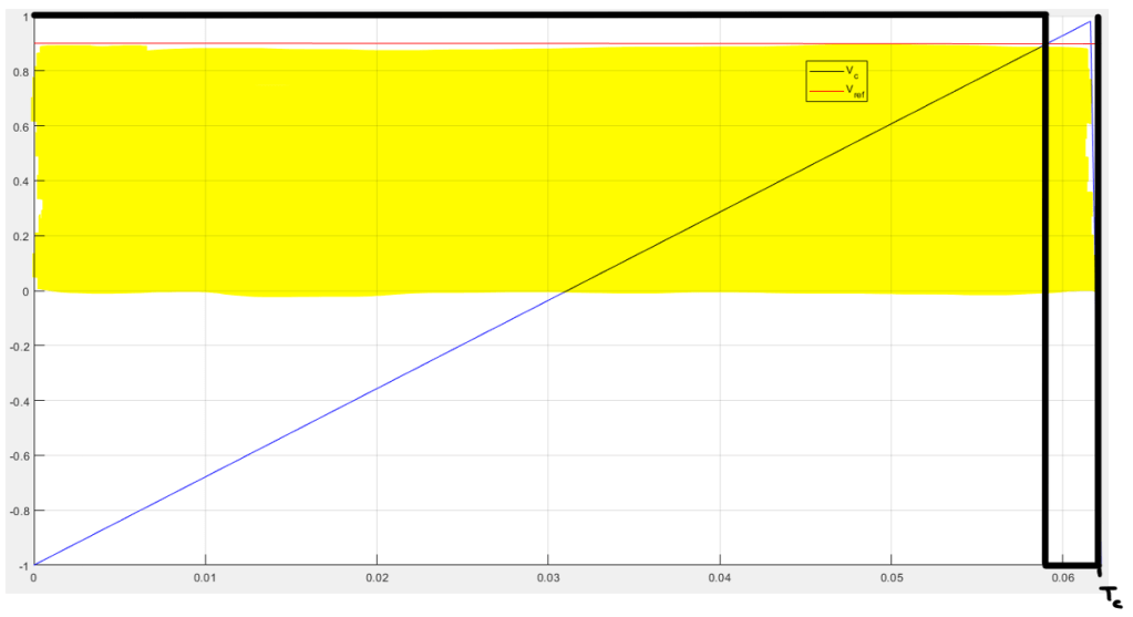
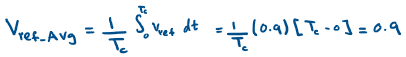
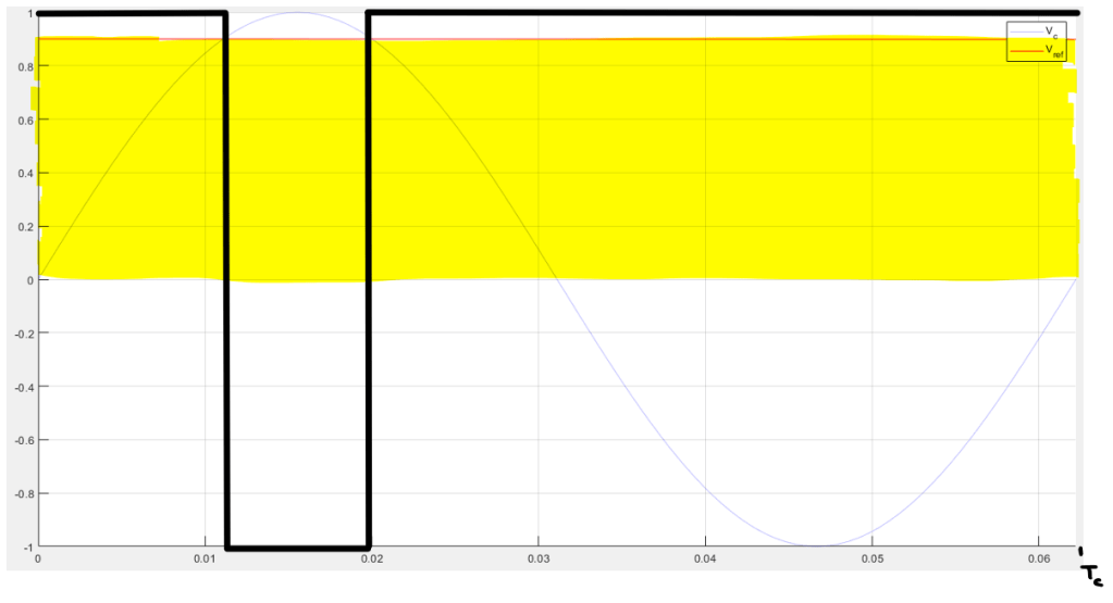
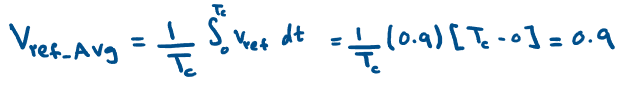
The Yellow highlighted region is the total Vref area during one carrier cycle. Then the average Vref value during this cycle is given by
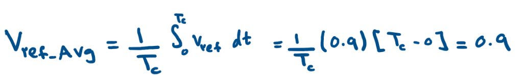
|| Side Note: Here we assumed that Vref is constant, but this is a good estimate if fc is much bigger than f0 ||
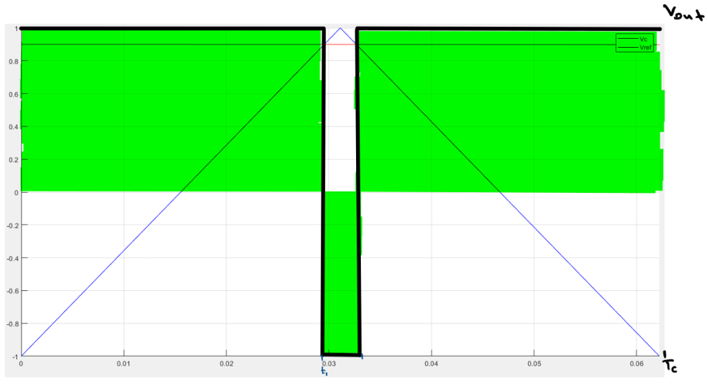
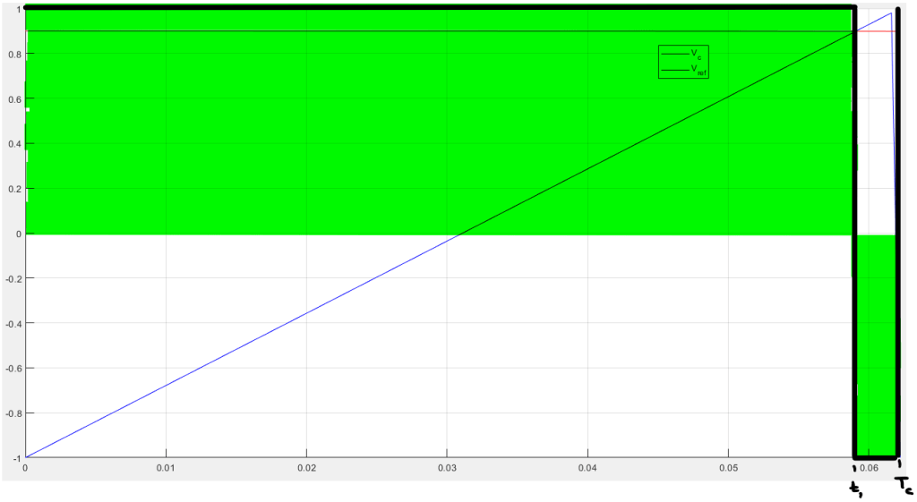
The Green highlighted region is the total Vout area during one carrier cycle. Then the average Vout value during this cycle is given by
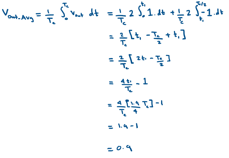
By equating their averages we ensured that their overall voltage is equal but what differs is how the voltage is distributed during the carrier interval Tc. So in an essence, Vout and Vref are equal so is the energy that is provided by both of them.
Another observation that is worth noting is that Vout during this interval Tc can be broken down into its Fourier series components, and this is the source of all the carrier harmonics in the overall Vout output.
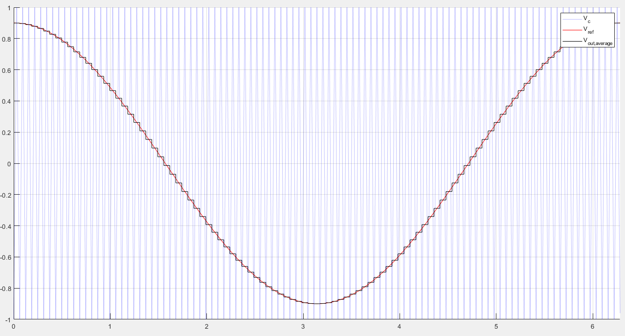
Finally, If we plot the average values of Vout during all Tc intervals, we observe that the averages trace Vref precisely except for some instantaneous differences which correspond to the side band carrier harmonics as we will see in the next lesson.
Saw-tooth Carrier
The same applies for the Saw-tooth waveform, if we zoom into one carrier cycle we get
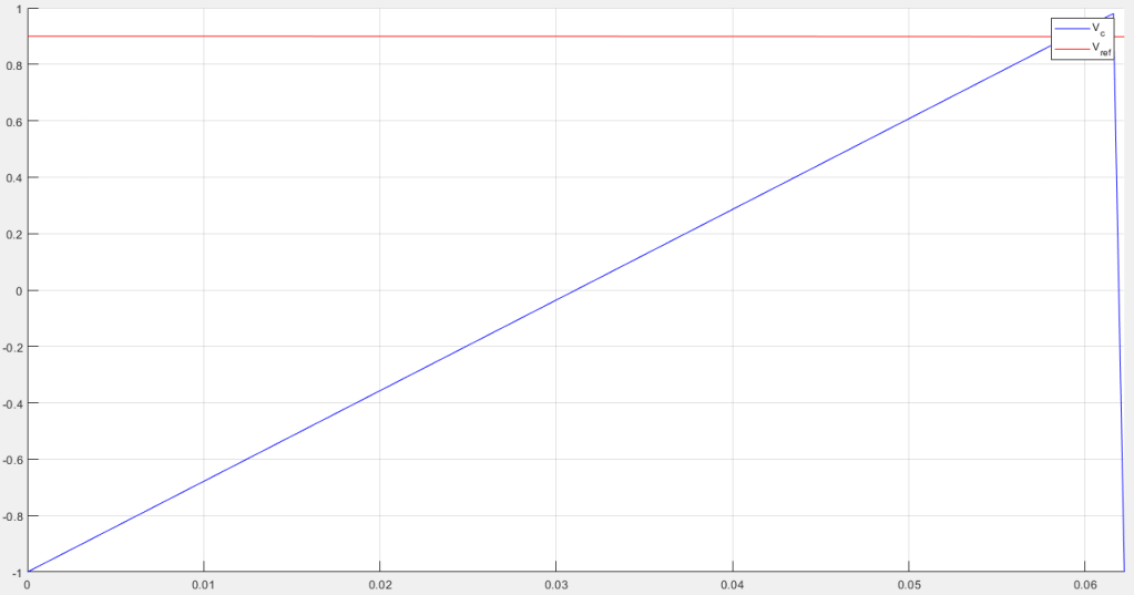
|| Side Note: The Saw-tooth looks distorted at the end because the matlap plotting function interpolates values in between to avoid sudden changes, but this affects only the visual appearance. In other words, just pretend it looks right.||
When we calculate the averages we get:
Here, too the averages are equal.
Ok, so now we established that our criteria for an acceptable carrier is that it can give us an output whose average equates the average of the reference signal.
Lets test this criteria against a different carrier and see if it holds, lets take a sine signal as a carrier.
Sine Carrier
Lets test the Average Value Criteria against a sine signal as a carrier.
Lets now zoom into one carrier interval and check if the Outputs average equals the reference’s average.
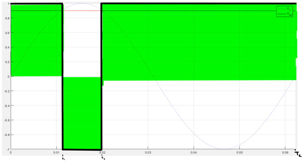
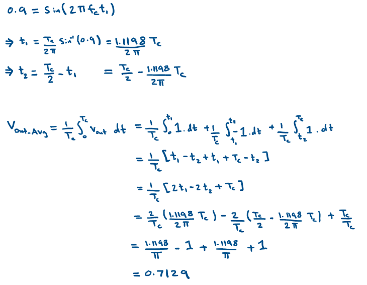
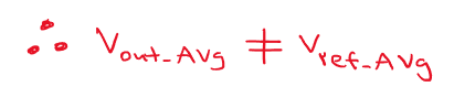
Since the Sine signal carrier is unable to produce an output whose average equals the average of the reference signal during each carrier interval, then sine signals are not a good choice for a carrier signal.
Back to the original question of this lesson, the reason we restrict ourselves to a saw-tooth or a triangular signals as carriers is that they preserve the average output of the desired reference.
In the next lesson, we will compare the saw-tooth and the triangular references by deriving their corresponding analytical harmonic expressions.

One thought on “Why always Saw-tooth or Triangular Carriers in PWM?”