In the previous post, we developed an analytical expression which pinpoints the harmonic content produced by the PWM procedure. We can now utilize that expression to examine the two most widely used carriers; the Saw-tooth and Triangular carriers.
But before we compare the Saw-tooth and Triangular carriers, I invite you to check the previous article which discusses why we restricted ourselves to these two carriers in particular in the first place? Why always Saw-tooth or Triangular Carriers in PWM?
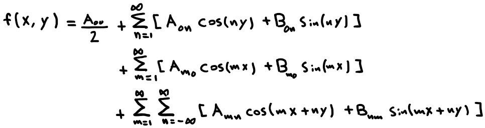
If we recall the double Fourier Series Expression we derived in an earlier article that

We can tidy this expression a bit by clustering the following terms:
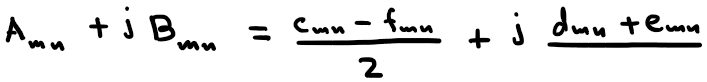
where

By doing so, we can rewrite the Full double Fourier Series as:
The effective difference between saw-tooth and Triangular carriers lies in Eq.1 as its integration result changes as we change in x and y.
Recall that

Also, instead of integrating over the full range of f(x,y), we should only consider the non-zero portion. Lets construct the Unit cell for a single phase Half-bridge(Single leg) inverter, where a Unit Cell is a 2-diminsional square cell that spans x in its x-axis and spans y in its y-axis, and any highlighted point in the cell indicates that the inverter is on in that corresponding portion.
Saw-tooth Carrier
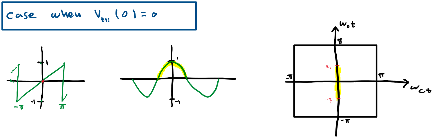
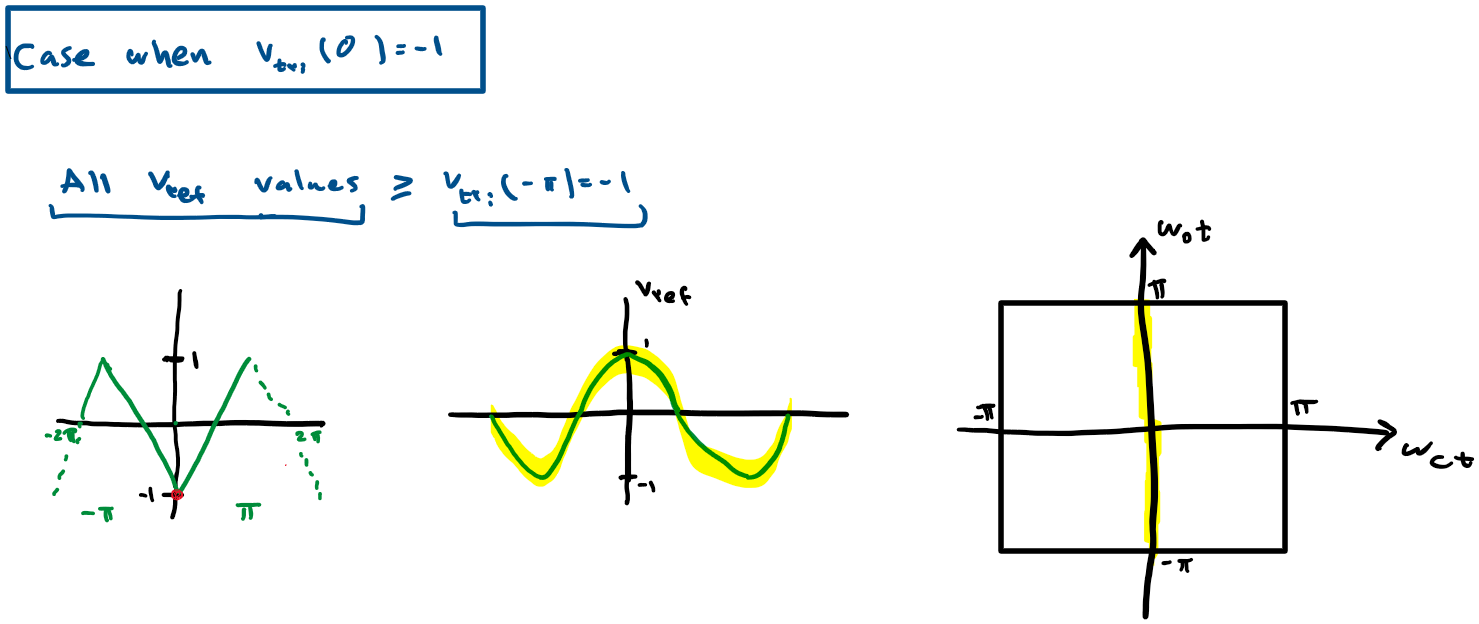
lets take a saw-tooth and consider the point where we are at x=-π and identify all points in y where Vref >= Vst
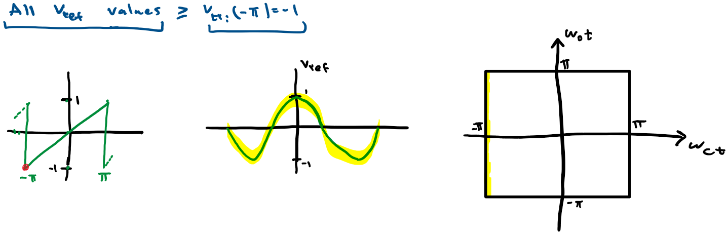
The Highlighted portion in Vref and in the Unit Cell correspond to the region where Vref >= Vst
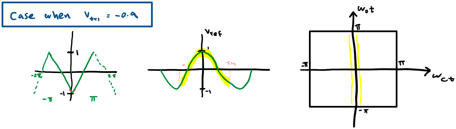
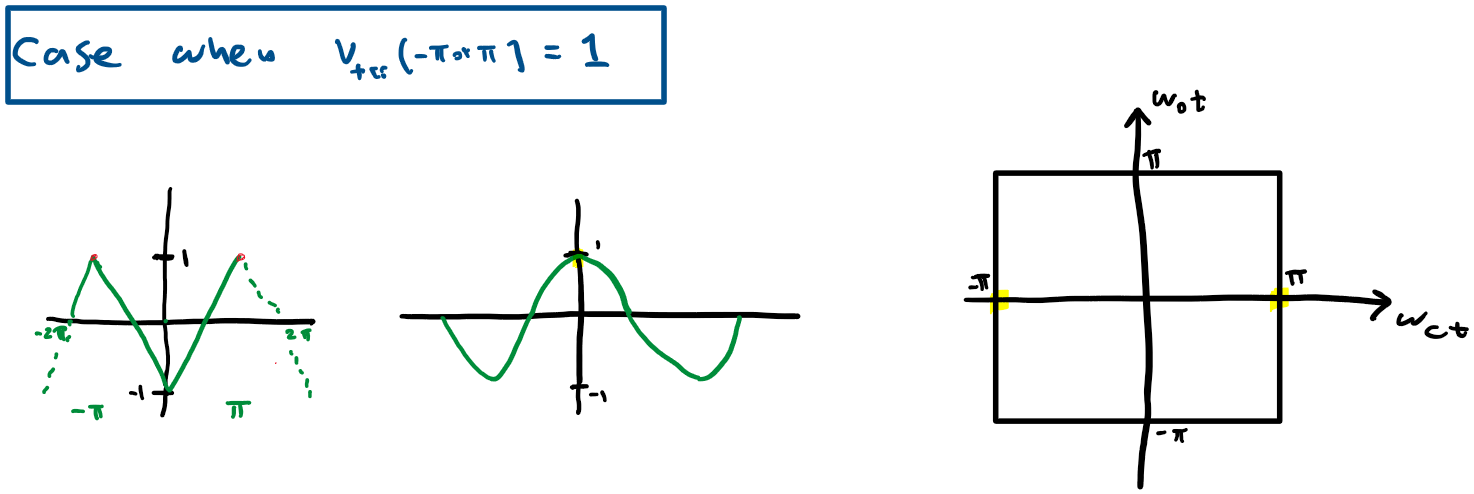
if we consider different points in Vst we get:
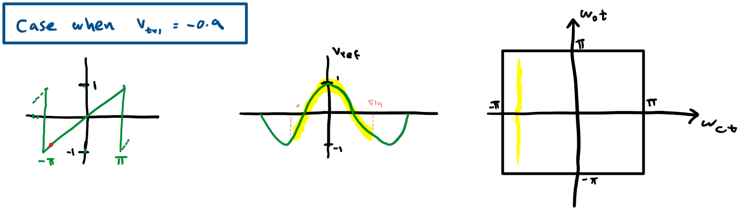
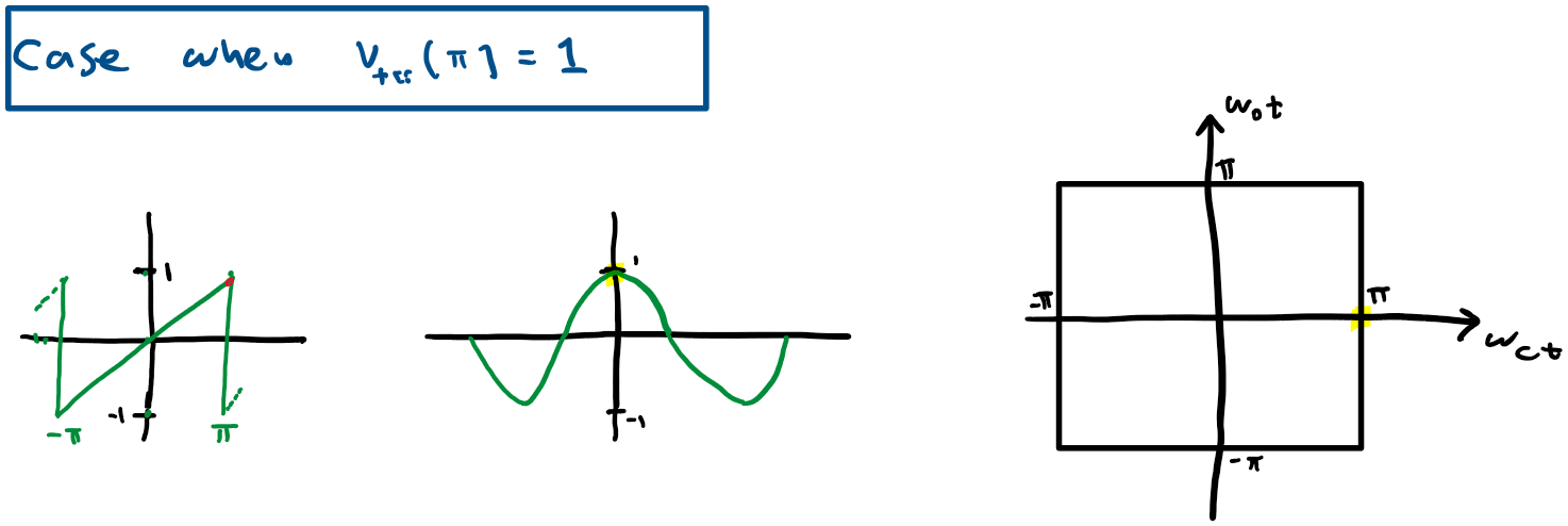
Doing the same for all points in x we get the following Unit Cell
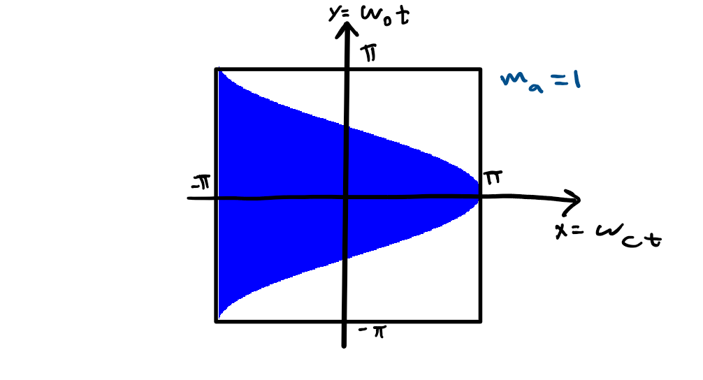
Notice that this is a Unit cell form the case when the modulation index ma=1 but we can do a similar evaluation and obtain a similar Unit cell for different values of ma

Looking at the Unit cell we observe that as y goes from -π to π, x goes from -π to πmacos(y).
Therefore Eq.1 becomes:

if we solve Eq.1 and plug it into Eq.2 we get:
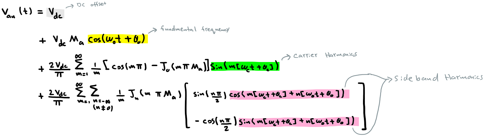
where the term J is called the Bessel function.
We observe from the final term in Eq.3 that:
- The are no Baseband Harmonics (no ‘n’ multiple harmonics of the fundamental)
- There are Carrier Harmonics (‘m’ multiples of the carrier frequency)
- There are Sideband Harmonics( ‘n’ fundamental multiples around ‘m’ carrier multiples)
Triangular Carrier
Similarly, we can get a double Fourier term for the case of a Triangular Carrier. We start by constructing the Unit Cell for the Triangular Carrier.

The complete Unite Cell for all values of x is:
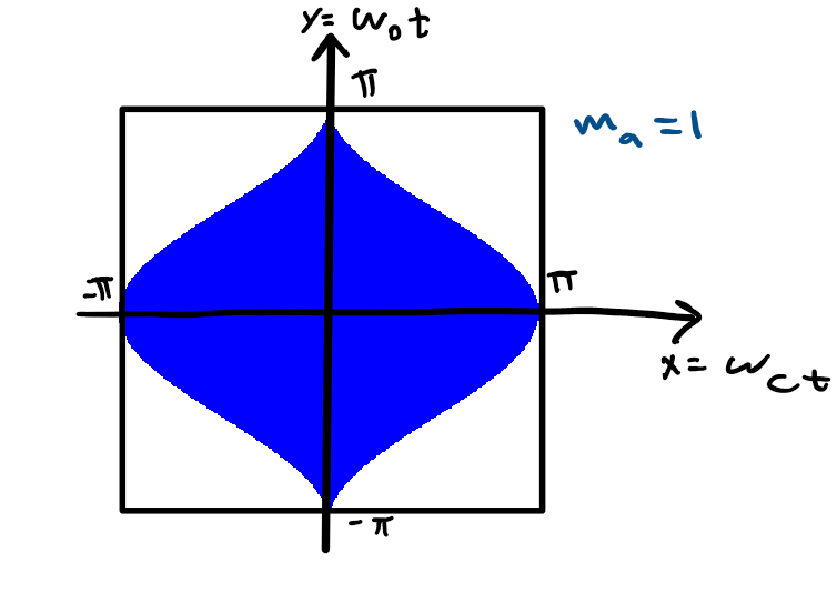
Similarly the unit cell changes slightly for different modulation index ma:

Looking at the Unit cell we observe that as y goes from -π to π, x goes from -πmacos(y) to πmacos(y).
Therefore Eq.1 becomes:

if we solve Eq.1 and plug it into Eq.2 we get:
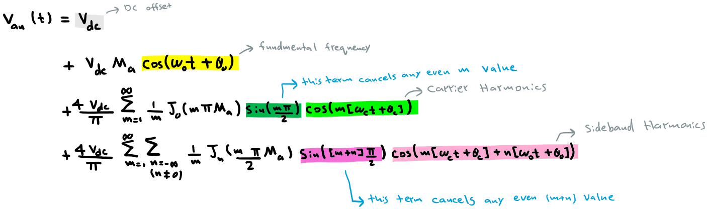
We observe from the final term in Eq.4 that:
- The are no Baseband Harmonics (no ‘n’ multiple harmonics of the fundamental)
- There are Carrier Harmonics (‘m’ multiples of the carrier frequency). However, all even Carrier Harmonics are Canceled.
- There are Sideband Harmonics( ‘n’ fundamental multiples around ‘m’ carrier multiples). However, all even sideband harmonics are canceled (if m and n are even or if m and n are odd).
In conclusion,
we can see a clear advantage of using a triangular Carrier over the use of a Saw-tooth Carrier due to the elimination of even carrier harmonics and even sideband Harmonics in the Triangular Carrier case. However, if the frequency modulation ratio is large enough, their performances becomes very similar because all Carrier Harmonics and Sideband Harmonics get vanish quickly.
References
D. G. Holmes and T. A. Lipo, Pulse Width Modulation for Power Converters. 2003.
