
This post may seem like a massive leap from the preceding posts, you may look at the title and ask yourself; what is SVM and whats reverse sequence. Well, you don’t need to bother with any of that. If you know… good, if you don’t that’s fine you will still benefit from the findings presented.
But to give some brief background, SVM is a special type of modulation in the sense that we have control over how each on and off pulse behaves, as opposed to the well-known sinusoidal carrier based PWM where the on and off pulses are generated automatically by comparing the sinusoidal reference with a carrier. Reverse sequence refers to the fact that in SVM each carrier period is divided in two mirroring images as seen in Fig.1
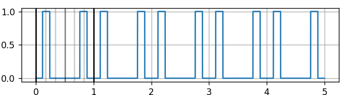
Having that out of the way, now what if we were to increase the width of this pulse or change the location of the pulse, what would happen to the harmonic response to the signal? Remember, after all the main advantage of SVM is that it gives us control over the carrier pulses’ location, so it would be pointless if we didn’t know what this extended degree of freedom do to our modulated signal.
So, we want to know the harmonic response of a signal, what do we do??? Take a second to think about it…
.
.
.
Yes, precisely. We should find the Fourier series expression of that signal.
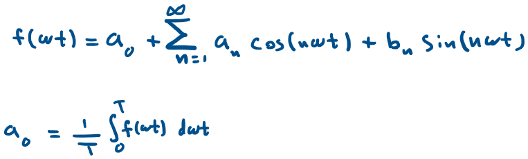
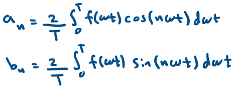
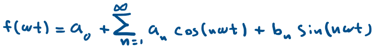
Recall, the Fourier series expression terms:
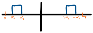
For the case of the reverse sequence signal in Fig.2, we will evaluate only over the non-zero region. The terms would solve to:
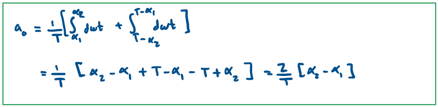
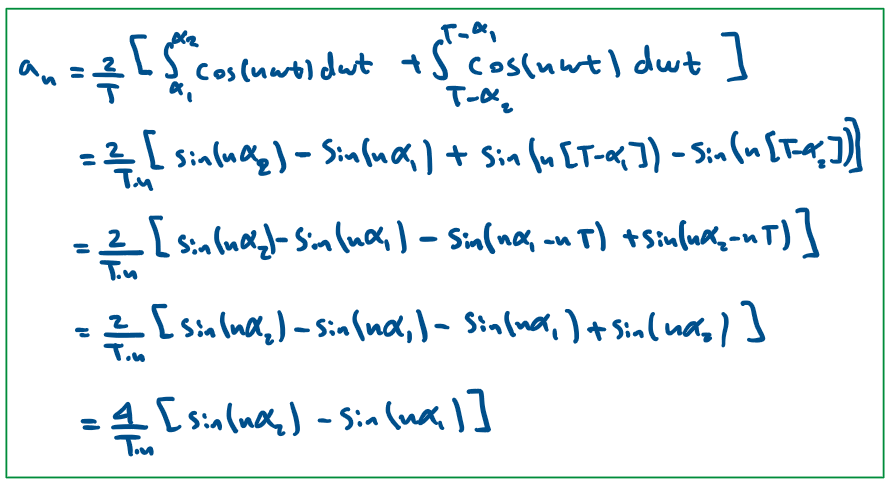
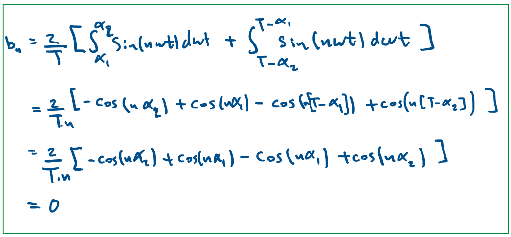
So the full expression will be:
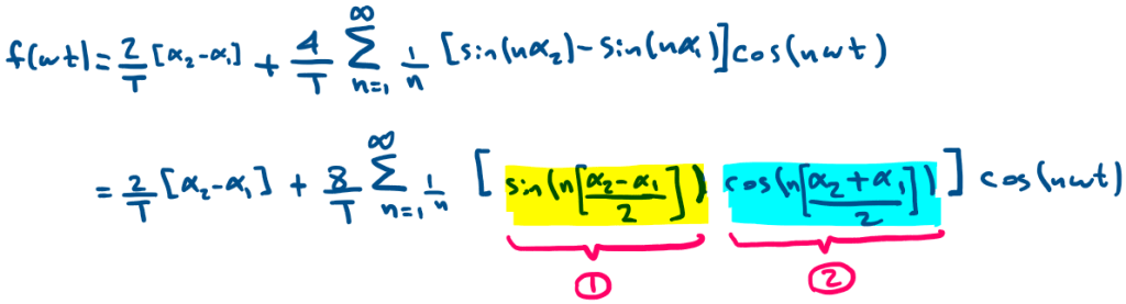
a0 is the DC term, bn is zero, and an can be analyzed to get some insight about the resulting harmonic performance.
First, by intuition:
α2 – α1 = The Pulse width (PW)
α1 + α2 = 2α1 + PW
1. The yellow highlighted portion represent a sine term that we know will cancel when
sin(n[ α2 – α1 ]/2) equals either sin(0) or sin(π). since we are not interested at the case when α2 – α1 = PW = 0 then:
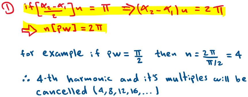
Notice the following interactive visualization for a case where PW= π /2, pay attention to the 4th,8th,12th,… harmonics and notice how no matter where the pulse is located those harmonics will cancel out.
This makes sense because the Sine term is determined by the pulse width only regardless of pulse location.
2. The turquoise(blue) highlighted portion represent a cosine term thus it will cancel when
cos(n[ α2 + α1 ]/2) equals cos(π/2).
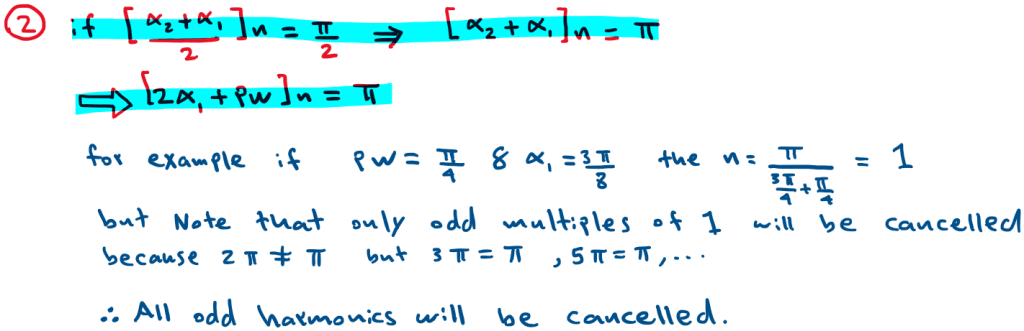
Notice the following example for a pulse width PW= π/4 and observe all odd harmonics will cancel once the pulse is at α1 = 3π/8 = 1.178 but if α1 is anywhere else the odd harmonics are present.
Also Note that this pulse location is the center of half the period. Hence, whenever the pulse is centered, all odd harmonics will cancel out.
3. The turquoise(blue) highlighted cosine portion will also cancel out some harmonics if the pulse width is an even division of π that is if PW= π /’even number’ and α1 = π /’2*even number’, then the harmonic canceled will be ‘even number/2’
for example if PW= π / 4 and α1 = π / 8 = 0.3926 then the harmonic canceled will be 2. As seen in Fig.5
Therefore, the pulse width and pulse location will have an impact on the harmonic performance of the signal, and this degree of freedom to control the pulse location makes SVM a very attractive modulation scheme for research.
To Experiment with the visualization tool used in this post, please visit the link
